


How to Implement a Switched Reluctance Motor Drive?
In order to implement an SR motor drive, it is necessary at least to acquire information related to the rotor position. This can be achieved by mean of a rotor position sensor. The type of position sensor used is dependent on two main factors, i.e. the resolution of the rotor position required in the drive and the cost of sensor. Each phase of the SR motor can be controlled independently by using power electronic switches such as IGBT and diode. An asymmetric bridge circuit as shown in Figure 10 is suitable for this purpose since an SR motor does not require bi-directional current control. In addition, a control logic circuitry is utilised so that based on the information of the rotor position, appropriate signals are generated to turn-on and turn-off the IGBTs of each of the phases in correct sequence.
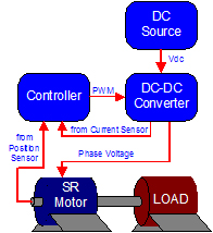
Figure 11 shows the block diagram of a SR motor drive. In addition to the rotor position sensor, a current sensor is used to measure the phase current for the current feedback loop of the drive. In this configuration, both the rotor position and phase currents are feedback to the control logic block which generates the appropriate gate drive signal to the IGBTs.